 |
 |
The furnace wall and
the side wall are made of a membrane wall structure
facilitating pressurized combustion to improve insulation
effect and boiler efficiency and to minimize thermal
loss. |
|
|
|
A cleaning hole facilitates cleaning
of the heating pipe.. |
|
|
|
Special plates for prevention of
carry over improve the dryness of the vapor and
improve the vapor efficiency. Also, the lifecycle
of the heat discharging facility and the pipeline
are extended. |
|
|
|
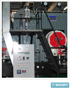
A simple structure and a small installation
area size allows you to assemble and install it
on-site. You can install it in an area with a small
opening. |
|
|
|
 |
|
| Model |
B&B-P |
100 |
150 |
200 |
250 |
300 |
400 |
500 |
600 |
700 |
800 |
1000 |
1200 |
1500 |
2000 |
2500 |
3000 |
3500 |
4000 |
| Rated
evaporation |
㎏/h |
1000 |
1500 |
2000 |
2500 |
3000 |
4000 |
5000 |
6000 |
7000 |
8000 |
10000 |
12000 |
15000 |
20000 |
25000 |
30000 |
35000 |
40000 |
| Gas
flow |
pass |
3 |
2 |
| Insulation
area size |
Boilerr |
|
29 |
37 |
45 |
55 |
62 |
72 |
86 |
104 |
119 |
136 |
170 |
204 |
250 |
335 |
415 |
475 |
555 |
635 |
| Air
heater |
|
- |
- |
- |
- |
- |
- |
40 |
49 |
55 |
65 |
78 |
92 |
118 |
156 |
198 |
232 |
275 |
322 |
Fuel
con-
sumption |
B/C |
ℓ/hr |
78 |
117 |
156 |
195 |
234 |
312 |
390 |
467 |
532 |
609 |
761 |
913 |
1141 |
1522 |
1902 |
2282 |
2663 |
3043 |
| LNG |
N㎡/hr |
70 |
104 |
139 |
174 |
208 |
278 |
347 |
416 |
475 |
542 |
678 |
814 |
1017 |
1357 |
1695 |
2035 |
2374 |
2713 |
| Valve |
Main
vapor |
A |
65 |
80 |
80 |
80 |
100 |
100 |
125 |
125 |
150 |
150 |
200 |
200 |
200 |
200 |
250 |
250 |
300 |
300 |
| Safety |
A |
25 |
40 |
40 |
40.25 |
40.25 |
40.25 |
40x2 |
40x2 |
40.50 |
50x2 |
50x2 |
50.65 |
65x2 |
65.80 |
80x2 |
80.100 |
100x2 |
100x2 |
| Water
supply |
A |
25 |
40 |
40 |
40 |
40 |
40 |
50 |
50 |
50 |
50 |
50 |
50 |
65 |
65 |
65 |
80 |
80 |
80 |
| Water
drainage |
A |
40 |
40 |
40 |
40 |
40 |
40 |
50 |
50 |
50 |
50 |
50 |
50 |
50 |
65 |
65 |
80 |
80 |
80 |
| Pressure
meter |
A |
25 |
25 |
25 |
25 |
25 |
25 |
25 |
25 |
25 |
25 |
25 |
25 |
25 |
25 |
25 |
25 |
25 |
25 |
| Water
level meter |
mm |
220 |
220 |
220 |
220 |
220 |
280 |
280 |
280 |
280 |
280 |
280 |
280 |
280 |
280 |
280 |
280 |
280 |
280 |
| Fuel |
B/C |
A |
20 |
20 |
20 |
20 |
20 |
25 |
25 |
25 |
25 |
25 |
25 |
40 |
40 |
50 |
50 |
50 |
50 |
50 |
| LNG |
A |
25 |
40 |
40 |
40 |
40 |
40 |
50 |
50 |
80 |
80 |
80 |
80 |
100 |
100 |
100 |
100 |
100 |
125 |
| Boiler’s
weight |
Ton |
8.2 |
10.1 |
11.7 |
12.8 |
13.4 |
15.0 |
18.6 |
19.2 |
21.5 |
24.7 |
29.5 |
33.2 |
36.5 |
44.9 |
52.3 |
55.6 |
67.2 |
73.8 |
| Quantity |
㎡ |
2.2 |
2.5 |
2.6 |
3.0 |
3.6 |
4.2 |
4.9 |
5.2 |
6.3 |
7.5 |
8.5 |
8.8 |
9.4 |
13.2 |
14.95 |
16.2 |
18.5 |
20.5 |
| Outlet
gas duct |
mm |
200
x400 |
250
x500 |
250
x600 |
250
x650 |
300
x750 |
350
x850 |
350
x1050 |
350
x1220 |
500
x1000 |
500
x1220 |
600
x1220 |
700
x1220 |
850
x1220 |
900
x1520 |
1015
x1720 |
1100
x1900 |
1100
x2200 |
1220
x2400 |
| Chimney |
mm |
300 |
360 |
430 |
460 |
500 |
550 |
610 |
680 |
750 |
820 |
900 |
960 |
1050 |
1350 |
1400 |
1500 |
1750 |
1950 |
Installa-
tion exterior |
Width |
mm |
2020 |
2100 |
2150 |
2240 |
2240 |
2300 |
2450 |
2560 |
2560 |
2700 |
3200 |
3200 |
3300 |
3600 |
3950 |
3950 |
4260 |
4560 |
| Depth |
mm |
3050 |
3350 |
3400 |
3500 |
3760 |
4470 |
4820 |
4820 |
4860 |
4950 |
5150 |
5650 |
5780 |
5920 |
6150 |
6830 |
7270 |
7520 |
| Height |
mm |
2260 |
2350 |
2460 |
2590 |
2675 |
2750 |
2900 |
3100 |
3150 |
3520 |
3610 |
3610 |
3850 |
4210 |
4520 |
4520 |
4920 |
5180 |
|
|
1. These specifications are subject to change depending on the customer's request and for the purpose of quality improvement.
2. Design pressure: 10kg/km2 (operational pressure: 8kg/km2)
3. Water temperature: 20℃,
4. Gas supply pressure is 2,000~4,000 mmA1 |
 |
 |
 |
 |
|
|
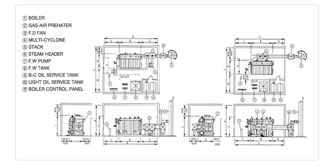
| MODEL |
B&B-P |
150 |
200 |
300 |
400 |
500 |
600 |
700 |
800 |
1000 |
1200 |
1500 |
2000 |
2500 |
3000 |
3500 |
4000 |
| A |
2020 |
2100 |
2150 |
2240 |
2300 |
2450 |
2560 |
2560 |
2700 |
3200 |
3200 |
3300 |
3600 |
3950 |
3950 |
4260 |
4560 |
| B |
3050 |
3350 |
3400 |
3760 |
4470 |
4820 |
4820 |
4860 |
4950 |
5150 |
5650 |
5780 |
5920 |
6150 |
6830 |
7270 |
7520 |
| C |
2500 |
2500 |
2500 |
2500 |
2500 |
1400 |
2000 |
2000 |
2400 |
2400 |
4000 |
4000 |
4000 |
4000 |
4500 |
4500 |
4500 |
| D |
3000 |
3100 |
3300 |
3800 |
4100 |
4400 |
4400 |
4500 |
4500 |
4000 |
4000 |
4000 |
4500 |
5000 |
5000 |
5500 |
6000 |
| E |
8550 |
8950 |
9200 |
10060 |
11070 |
11720 |
11970 |
11360 |
11450 |
12650 |
13150 |
13780 |
14420 |
15150 |
16330 |
17270 |
18020 |
| F |
7020 |
7100 |
7150 |
7240 |
7800 |
7950 |
8060 |
8060 |
8200 |
8700 |
8700 |
9300 |
9600 |
9950 |
9950 |
11060 |
11360 |
| G |
2350 |
2400 |
2450 |
2550 |
2600 |
2750 |
2900 |
2700 |
2900 |
3400 |
3400 |
3500 |
3800 |
4250 |
4250 |
4500 |
4800 |
| H |
4000 |
4000 |
4000 |
4000 |
4500 |
4500 |
4500 |
4500 |
4500 |
4500 |
4500 |
5000 |
5000 |
5000 |
5000 |
5800 |
5800 |
| I |
2260 |
2350 |
2460 |
2675 |
2750 |
2900 |
3100 |
3150 |
3520 |
3610 |
3610 |
3850 |
4210 |
4520 |
4520 |
4920 |
5180 |
| J |
2250 |
3650 |
2800 |
3000 |
3050 |
3200 |
3300 |
3450 |
3850 |
3950 |
3950 |
4150 |
4550 |
4850 |
4850 |
5250 |
5500 |
| K |
3360 |
3750 |
3860 |
4100 |
4150 |
4300 |
4500 |
4550 |
4950 |
5000 |
5000 |
5250 |
5600 |
5950 |
5950 |
6350 |
6600 |
|